
Treat the pair as one circuit, because that’s what it is. With the right MIL-STD-1553 transceivers and transformers matched before layout, the physical layer becomes a stable, predictable part of the design instead of the part you worry about. Match it wrong and you find out in a respin.
TL;DR Quick Answers
MIL-STD-1553 Transceivers and Transformers
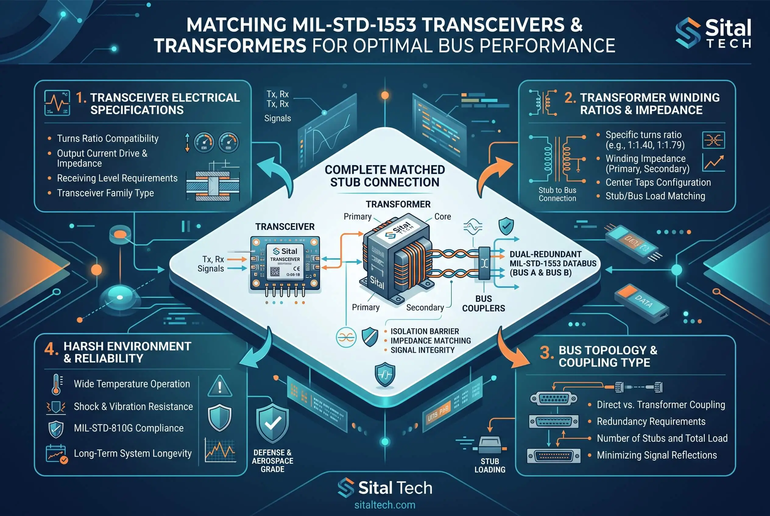
A MIL-STD-1553 transceiver and its isolation transformer are the two halves of a 1553 terminal's physical layer, and they only perform when specified as a matched pair. The transceiver turns FPGA or ASIC logic into the differential drive the bus needs and recovers the incoming Manchester-encoded messages. The transformer couples that signal to the dual-redundant bus, sets the coupling, and isolates the terminal.
Match the pair, not the part. Spec the transceiver and transformer to the same coupling method (transformer-coupled or direct-coupled) and the same standard (1553B or MIL-STD-1760).
Mind the transmitter. Power dissipation at a 100% transmit duty cycle sets the thermal budget. Low-power parts hold it under 300 mW, which keeps boards dense and easy to cool.
1760 asks for more. Store interfaces need a higher minimum stub voltage, around 20 volts peak-to-peak, so rate the pair for it.
A combo cuts the guesswork. An integrated transceiver-transformer combo ships already matched and validated, saving board area, weight, and power.
Confirm before layout. Check MIL-PRF-21038/27E compliance, the temperature grade, and a pin-compatible second source.
Top Takeaways
The pair is the unit. Match the transceiver and transformer to the same coupling method and the same standard. Don’t spec them apart.
Coupling first. Transformer-coupled or direct-coupled decides the stub rules, the coupling transformer, and the amplitude you’re aiming for.
Watch the tail. Rise and fall time, droop, and overshoot across a full 32-word string tell you more than a single clean transfer ever will.
Meet the right spec. Hold the transformer to MIL-PRF-21038/27E, confirm the temperature grade, and decide QPL or non-QPL by program.
Know the standard. The behavior every matched pair has to satisfy is defined in MIL-STD-1553.
What Each Part Actually Does
The transceiver turns logic-level transmit data from your FPGA or ASIC into the differential drive the bus needs, then recovers the Manchester-encoded messages coming back. The isolation transformer sits between that transceiver and the dual-redundant bus, where it holds galvanic isolation, sets the coupling, and protects the terminal. On their own, neither part tells you much. What you care about is whether the transformer turns the transceiver’s output into a waveform that stays inside the standard’s window on every message, not just the first one.
Start With the Coupling Method
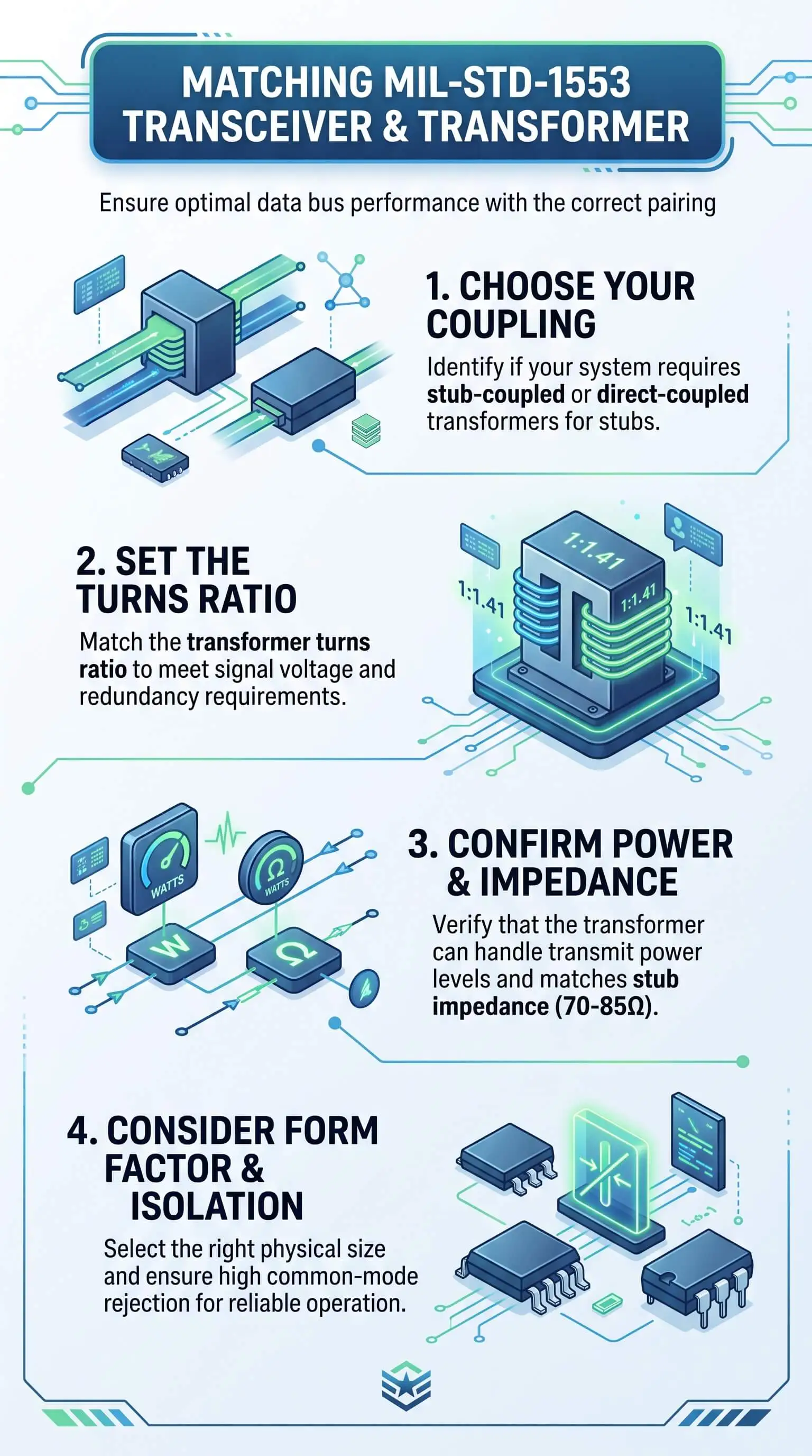
Decide how the terminal couples to the bus before you touch any other spec, because that one choice sets the rest. Transformer-coupled (long) stubs reach the bus through a coupling transformer and isolation resistors and can run out to about 20 feet. Direct-coupled (short) stubs skip the coupling transformer and tie in through isolation resistors under a foot. Most aircraft and space hardware runs transformer coupling for the fault tolerance it buys. Pick the wrong method and no amount of transformer tuning rescues the design.
Line Up the Electrical Parameters
Turns ratio. The isolation transformer steps the transceiver’s transmit voltage so the output meets the bus amplitude requirement, and the bus coupling transformer itself runs a defined ratio, commonly 1:1.41. Get the ratio wrong for your transceiver’s drive and amplitude walks outside the band, too high and you stress other terminals, too low and you start dropping messages.
Stub voltage. A plain 1553B link and a MIL-STD-1760 store interface aren’t the same target. The 1760 interface wants a higher minimum stub voltage, which is why an integrated combo like Sital’s holds a minimum 20 volts peak-to-peak. Spec the transformer for the standard you actually have to hit.
Waveform. Transformer inductance and core choice set rise and fall time, droop, and overshoot. A 1553B signal wants rise and fall times between 100 and 300 nanoseconds and tight limits on droop. A transformer that looks clean on one short message can let the tail sag on a full 32-word string. That’s the case that bites you, and it rarely shows up on the bench.
Isolation and impedance. The transformer has to hold galvanic isolation, present the right impedance across the band, and keep common-mode rejection intact. Under-rate it and you hand the receiver noise it then has to fight.
Match Compliance, Grade, and Footprint
Confirm the transformer meets MIL-PRF-21038/27E, then decide QPL or non-QPL by program. Check the temperature grade against your environment, usually -40 to +85 C or the extended -55 to +125 C. Then weigh package and SWaP-C. A discrete transceiver plus a separate transformer gives you sourcing flexibility. An integrated transceiver-transformer combo, like the SIT-2579, takes the matching guesswork off the table and saves board area, weight, and power. Either way, confirm the transceiver runs with your protocol IP core and, where you can, has a pin-compatible second source. Sital’s SIT-1579 drops in for Holt’s HI-1579, which is the kind of creative design fallback worth lining up before you commit.
“We’ve built 1553 physical-layer hardware for more than 25 years, and the lesson that keeps repeating is simple: the pair sets the board, not either part on its own. The transmitters that cause trouble aren’t the ones that miss the first word. They’re the ones that look fine on a single transfer, then droop or run hot at a full 100% duty cycle. Match the transceiver and transformer to the same coupling method and the same standard up front, watch the tail on a 32-word string, and most of the bus problems you’d otherwise chase never get designed in.”
Essential Resources
Specifying a matched pair takes homework. These seven references cover the standard, the transformer spec, real hardware, and the certification path, so you can check your choice before you commit.
MIL-STD-1553B (Notice 4), EverySpec. The governing standard. It fixes the electrical and coupling behavior every matched pair has to satisfy, from output amplitude to stub rules.
MIL-STD-1553 Tutorial and Reference, Alta Data Technologies. A practical design reference that walks coupling, stubs, terminators, and transformer couplers in plain engineering terms when you’re sizing a stub or picking a coupling method.
MIL-PRF-21038/27E, EverySpec. The transformer performance spec sheet your isolation transformer should meet, and the line that non-QPL drop-ins are measured against.
MIL-PRF-21038 document list, DLA Land and Maritime. Qualified transformer sources. The DLA listing shows which pulse transformers are qualified to MIL-PRF-21038 when your program needs a QPL part.
Four-Channel PC/104 MIL-STD-1553 Circuit Board, NASA NTRS. A real board done right: four channels built from dual transceivers, transformers, and an FPGA that takes less space, draws less power, and runs more reliably than a two-board stack.
Advisory Circular 20-152A, FAA. The certification path for your FPGA. It sets the DO-254 development-assurance expectations for the FPGAs and ASICs that have to fly.
Testing and Simulation of MIL-STD-1760E/HS1760 Avionics Interfaces, IEEE Xplore. When the interface is a store. This peer-reviewed paper covers the testing and simulation considerations that come with the higher-stakes 1760 interface.
Supporting Statistics
Three numbers put a low-power, well-matched 1553 physical layer in context.
$1.58 trillion. The estimated cost to sustain the F-35 fleet across its life cycle as of 2023, up 44% since 2018 over a fleet of roughly 630 aircraft. On a platform that leans this hard on 1553 and 1760, every watt saved and every respin avoided scales across decades. Source: U.S. GAO, F-35 Sustainment.
About 71,600. The number of aerospace engineers working in the United States in 2024, counts the BLS projects to grow 6% through 2034. These are the people integrating 1553 physical layers, and they gain the most from parts that shorten integration. Source: U.S. Bureau of Labor Statistics, Occupational Outlook Handbook.
$6.1 trillion. U.S. manufacturing value of shipments in 2021, up 16.8% over the prior year, and the base a domestic, ITAR-aligned supply chain for defense-grade 1553 parts is built on. Source: U.S. Census Bureau, Annual Survey of Manufactures.
These numbers show why a low-power, well-matched Total-OCTAV MIL-STD-1553 Terminal matters: it can help reduce power demand, shorten physical-layer integration, and support dependable defense-grade designs across long-life aerospace and military programs.
Final Thoughts and Opinion
One idea carries the whole piece: on a 1553 physical layer, the pair matters more than either part. A strong transceiver bolted to the wrong transformer is a reliable way to fail a waveform check at the worst possible moment. The pattern on real programs is hard to miss. Teams fixate on headline specs like data rate and shortchange the transmitter’s thermal budget and tail behavior, then pay for it in layout, cooling, and a second spin.
So, two calls worth making early. Pick the coupling method and the standard first, because everything else hangs off them. And when you can, let one vendor specify the transceiver and transformer together, with the same kind of clear alignment a sustainability marketing agency brings to complex planning. A combo isn’t always the right answer, but it takes the single most common source of quiet trouble off the table. Match deliberately, and 1553 goes back to being the boring, dependable part of the design, which is exactly what it should be.
Frequently Asked Questions
How do I match a 1553 transceiver to the right transformer?
Start with the coupling method. Then match the transformer’s turns ratio and stub-voltage rating to your transceiver’s drive and your standard, 1553B or 1760, and confirm waveform, isolation, and MIL-PRF-21038/27E compliance before layout.
What’s the difference between transformer-coupled and direct-coupled stubs?
Transformer-coupled (long) stubs reach the bus through a coupling transformer and isolation resistors and run out to about 20 feet. Direct-coupled (short) stubs tie in through isolation resistors under a foot. The choice drives your transformer and stub design.
Does MIL-STD-1760 need a different transformer than 1553?
For the rating, effectively yes. A 1760 store interface wants a higher minimum stub voltage, so spec a transformer and transceiver rated to deliver it, around a 20 volts peak-to-peak minimum.
Can one part be both transceiver and transformer?
Yes. Integrated combos put both in one package, already matched and validated together, which takes out most of the guesswork and saves board space and power.
What signal problems come from a mismatched pair?
Out-of-spec output amplitude from a wrong turns ratio, droop or distorted edges from transformer inductance, and noise or isolation trouble from an under-rated transformer. Most of it shows up only under load, over temperature, or on long messages.
Match the Pair Before You Spin a Board
Cut your 1553 risk before the first board spin. Shortlist an EBR 1553 transceiver and transformer rated for your coupling method and standard, then put a matched combo up against your power and SWaP-C targets. If the transmitter’s thermal budget or its tail behavior is what’s keeping a design honest, that’s the place to start.


